Engine, Prop and Fittings

With the engine now in place we connect up the propeller shaft and put in new gland packing and grease up.
(Unfortunately we were unable to procure a two blade propeller with the universal coupling so the three blade propeller was reinstalled and Peggy remained a coble that could not be beached because the propeller shaft had to remain in the locked down position – MD).

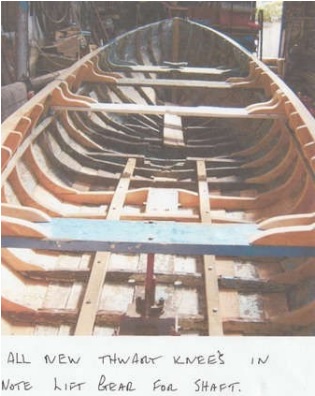
The propeller and shaft on this boat is unusual and becoming quite rare, it is designed to be lifted up between the bilge keels when the boat is beached, but also to reduce the drag effect when under sail the propeller is also unusual as it only has two blades enabling it to gain maximum height between the bilge keels.
Just to the front of the inspection box there is a stern gland installed in the vertical position the shaft through this has 2 holes drilled through for the 2 positions raised or locked down when in use.
To make this work the lift on the outboard propeller shaft close to the gland there is a universal joint then a second shaft goes into a swivel bearing on the end of the upright shaft. This works well and is a proven design, only problem it can rattle and vibrate a bit when in use.

Page 20.

Fittings

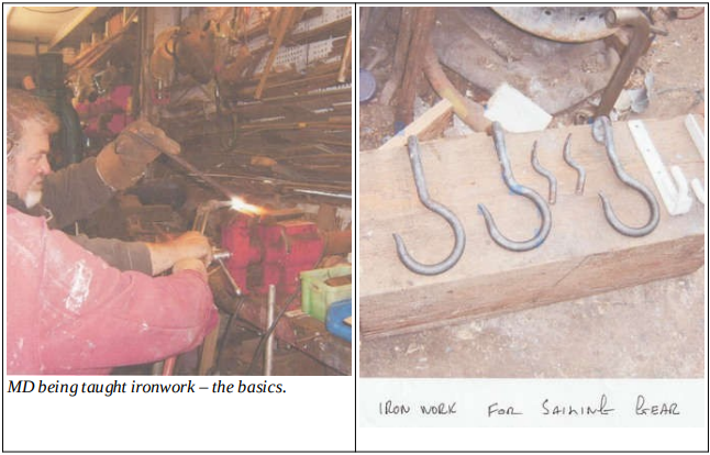
Now its time for a change in material. It’s iron work we need with the help of our faithful stove and the gas torch its making the sailing gear and the rudder fittings, lots of heat, the anvil and big hammers.
We make three large sailing hooks, two fixing points and two shroud plates.
Two plates to fit on the rudder with long pins, these are always about 9 inches long the reason being you don’t want the rudder to jump out the eye plates in bad weather. A plate for the bottom pin to fit through will be bolted through the base of the horseshoe and on the inside of these bolts a plate with a ring welded on to take the stern mooring ropes.
The top pin on the rudder goes through the back edge of the oak scut.

Page 21.

Posted in Peggy | Leave a comment

Fitting Out

Once the hull had been made sound and the droughts securely bolted to the new frames and the listings or listons relaced, work could start on repainting her on the outside and the inside attended to.

First of all the floorboards needed replacing and the same time the engine box needed some attention and it was decided to replace it completely to make it much easier to move around while trying to sail her. – MD 21-Apr-24

Fitting Out – per Fred Crowell

Now we start to refit the thwarts and fit the new knees these are cut with care to get the grain right. If not cut correctly these will fail at the short grain section. These will be fixed through the gunwhale as other fixings, with galvanized nails.
The working boats tend to use steel knees 2 inch x 1/2 flat bar with a 3/4 inch round bar welded on to form a triangle from gunwhale to thwart, this gives a very strong job and also the bar gives a tying up point for ropes fenders etc. The midship thwart on the larger boats usually has a bulkhead constructed on the aft edge this adds some strength but also creates a separation from the engine area and the working area.
The thwart midships and next forward usually have a plywood board resting between them this creates part of the engine cover also makes getting forward much easier.

Page 17.

Deck Floors

Next job to start is the floors and beams, we start by putting in the long beams these stretch from the base of the horseshoe to the engine beds, location is above the inside rail that holds the bilge keels, with such a long spread you will have to put in three uprights to support the load these will be cut to fit on and be fastened to a frame. Make sure that the timber comes short of the hull planking, reason being if on the planking a heavy load on the floors could push the planking away from frame causing a leak. With beams set we now do the inwires, these are the rails that run along the frames to support the floors on the outside edge. To get the correct height for these place a straight edge on top at the beams and mark the height on the frames, this will be about 2×1 inch due to the position on the frame the top corner, will need a lot of bevel off for the boards to lay flat normally about 3/4 inch is needed but don’t fasten in until the bevels are checked. You can’t take more off once nailed as this will make it to low. On the top of the main beams fix a lath 3/4 inch x the thickness of floor boards this gives the final position of hoards on beam.
With everything set off we now start on the boards the best way to do this will he to do the center boards first this will give a good working area to work from when fitting the sides. A bit more skill needed to fit the side floors as these run around the hull frames fit the boards but leave length on until the fit is right.
As the underside will need a lot of bevel off correct this later will make the boards short. New knees and scut fitted to transom top. Don’t make the boards to good a fit to frames, this will give any water a chance to escape the deck floor.

Page 18.

As the underside will need a lot of bevel off correct this later will make the boards short.
Don’t make the boards to good a fit to frames, this will give any water a chance to escape the deck floor.

Posted in Peggy | Leave a comment

The Stern Tube

These had to be replaced due to rot in the timber. The blocks are made up in oak between 2 frame spaces and through bolted, the forward bolts will have pads on them these cover 2 frames on the underside of hull. The outside block covers 2 frames through bolted these will have pads on the inside. The forward frame is made thicker and wider to take the face plate of the brass stern tube. This also gives better fixing as it is not end grain. This is reduced at the frame ends to match the existing frames.
When fitting the block we try to match up the existing bore hole on the bench this helps keeping things in line on the final bore of the tube.

Page 16.

Posted in Peggy | Leave a comment

Aft Scut & Listons

This is a broad piece of oak usually 2 inch thickness about 16 inches wide, it fits across the extreme back of the gunwhales and has 3 bolts through the gunwhales on each side, the reason for such a strong job is the pin for the rudder passes through this the coble rudder is usually quite long and about 15 inches wide this takes a great deal of strain and has a long tiller to allow the crew to hold it in place. The edges above the gunwhale are tapered and rounded down.
In the middle in front of the rudder pin hole there is a 2 inch hole through, this is for the aft mooring rope, the rope passes through to a plate with a ring welded on held in place with 2 bolts these bolts are through the base of the horseshoe and on the outside of the transom the bottom ring plate for the rudder.
The hole for the rudder pin should also have a stainless plate around it about 8 inches square with a 2 inch bend down the transom this is to protect the scut when shipping the rudder in and out.

There was no picture of the Scut taken at the time but here is one taken from the Quay in the centre of Newcastle in July 2013.

Page 14.


Listons or Landing battens.

Geordies prefer the name listons these are a hardwood rail that fits on the bottom edge of the planking and are made thicker than the planks, these act a protection for the plank edge from ropes, pots and nets, much easier to replace a liston than a new plank and these are usually about 1 and 1/2 inch x 1 inch rounded off on bottom the top edge just a corner off with the hand plane, some bevel off the top edge to fit the planking but each liston has a different bevel so dress each one and mark for location but try to stagger the joints, these will be fixed with a galvanized nail through the planking and into the frames this gives even more strength to the hull.
When all are ready find a place to give them two coats of paint, paint a strip of planking about 3 inches including the bottom edge of the plank above before fitting.
If not already done now is the best time to fill in the planking nails usually putty, and sand down to finish with the listons fit its difficult to get the sander in, but don’t paint yet as you need to see frame nails for fixing the listons.

Page 15.

Posted in Peggy | Leave a comment

The Gunnels

Depending on the size of the vessel these vary in thickness and width on the larger Yorkshire working vessels could be 5 inch by 3 inch but on the Peggy being a sailing coble they are much lighter at 4 inch by 2 inch, the top plank has a lot of tumblehome “means leaning inboard at top” this means a lot of bevel has to be removed to bring gunwhale flat at top, you can make a tool to help you determine this, rather than write a description a drawing and how to use accompany this page, but this can also be used on other parts where needed.
When fitting the gunwhales try to stagger the lengths on opposite sides of the vessel to give more strength, paint top 3 inches of plank and back of gunwhale before final fix. When steam bending the gunwhale timber is very difficult to set the cramps square, so to correct this we gut a block that will be square to the outside edge of the timber and cramp this to the frames inboard.
The base of this block is also square to the top of the timber this allows for the holding down position. If you don’t do this, due to the bevel on gunwhale, it will just keep rising up and jumping off the plank. See photograph for use of blocks. Don’t forget to leave length on the gunwhale timber to fit scarf joint, also on most cobles these extend past the transom to take the scut fixed on gunwhales across the back and above the transom. These often referred to as the horns.
When fixing the gunwhale the usual method is to drill the frame tops right through to take a 6 inch galvanized nail, but these are put in with the nail head on the inside this gives a stronger hold on frame top and will not split frame head top. On the outside these are plated over. Do the same with the drill as on fixing frames to sink the nail below surface. Don’t want any snags in way of net hauling.

Page 13.

Posted in Peggy | Leave a comment

New Planks

Next we place the plank templates on the new Larch planks. Always gut the planks to shape before planing this leaves the offcuts thicker for use elsewhere. Always leave some length on the planks if you have a problem with the scarf joint you can correct and move the plank along and cut the excess off when fixed to transom.
When fitting the top plank leave at least 1/2 inch on the top edge this will have a bevel on the top edge if you cut it exact it will get damaged when fitting the gunwhales it will be planed off when the gunwhale is fixed then a 2×1 and a 1/2inch chafe rail is fit to protect the plank, if it’s a working coble this top rail gets a lot of wear off the pot ropes and nets but is easier to replace than a gunwhale.
On the starboard side several frames and planks are replaced using the procedure as for port.

Page 12b.

Posted in Peggy | Leave a comment

Frames

Now we start removing the planking on the aft port section, taking great care to preserve the best template for the new plank, also to not damage the frames that need replacing, again good templates. These frames are replaced in oak and ash according to what timber we have to get the best grain.
The frames base lands on the lower gross frame. These are usually about 3 inch thick, much stronger, the reason being that the outside bilge keel will have through bolts to hold it in plage and an inside rail which settles on the frames above and the same length of the bilge keel this puts all the strength into the bottom of the vessel when all the bolts are in.
This creates a big clamp effect, keeping all the frames in plage, the frames at the base joint will have copper clenching in them but on the planking usually at 6 inch galvanized nail this is cut with an inch showing through then bent over into the frame with a man holding a big hammer on the outside. A good tip is to use a 1/4 inch drill to create a grove into the frame to take the bent over section this will allow the nail to be below the frame surface and a bit putty to tidy up frame face.
Several frames are replaced and primed.

Pictures from Pages 12 and 12b.

Posted in Peggy | Leave a comment

Transom

The transom or stern-back is made very strong as this has to take the lower rudder fitting with such a long rudder when put hard over the force is extreme hence the long tiller for crew to handle the load . This consists of 3/4 inch larch boards on the horizontal then a 3/4 inch larch board upright with copper clenching on every cross joint, the hull to planking has a 2 inch oak frame cut to shape this is called the horseshoe because of its shape, the lower section is about 1 inch wide oak with the sides reducing to 6 inch at the top.
When fitting the boards they must be fit from the inside due to the angle of the hull planking when fitting the base section of the horseshoe the top edge must be cut with a lot of bevel, due to the angle of transom if it was cut square to the hull this would cause a water trap and cause rot to happen on the long term again paint back before final fit, being at the waterline, this is also bedded in with a white lead paste. Put plenty on to ensure a water tight fit better to much than not enough you can clean up the excess and put it back in pot. Don’t waste it.
Now the side wings make a good template remember its 2 inch thick so put some 2 inch blocks on first to make template for where the front fits, if you don’t do this when you remove the back bevel to fit hull the timber will be under size, yet again paint before final fit. If you have to use two pieces to make the shape make the joint over 6 inches. This will give more room for fixings.

Page 11.

Posted in Peggy | Leave a comment

Stem

With the forward base section the keel in place, we then fit the knee or deadwood on top planning the position of the through bolts for more maximum strength, also made and fit is an anchor chain fixing eye this is welded onto a plate that fits over two of the through bolts instead of washers a much stronger job and no chance of breaking loose.
Next stage fitting the base section of the new stem, no template to make as we had the original to copy from rotten hut still in one piece. Next the upper part of the new stempost again a copy of original, now we fit the apron this is broader than the stem and when bevelled to the right set gives the landing area for the hull planking. The apron is made longer than the top stem section to keep the scarf joints apart for more strength.
Now its time to replace the forward planking removed to make easy repairs, hut before fixing a coat of paint is applied to the stem and apron. This is the only time they will get paint. Not exposed once planking done. Final touches, caulking along the keel seam on new planking and putty up the seams then a coat of grey primer.

We now plan out where to start next and we move onto the transom.

Page 10.

Posted in Peggy | Leave a comment

Forward-keel

Page 9 from Fred Crowell’ notes on the restoration of the 80 year old Coble – Peggy.

Note the template for
the deadwood is made
before the keel section
is cut out.

Light plywood templates.

Posted in Peggy | Leave a comment